

FlukeDAQ
This article will explain how to set up FlukeDAQ version 6.0.4 at a basic level, enabling you to configure a test and start a scan. This example presumes a beginning understanding of the 2638A and its software, as well as an understanding of the module and wiring connections.
Prior to following this article, it is assumed you have installed the Fluke Daq software and the USB drivers that were included on the DVD.
In this example we are using a 2638A with a 2638A-100 module in Slot 1, a k-type thermocouple on channel 2 of that module and USB connection to the computer. Please note that channel configuration follows the same steps regardless of the test type. This scan setup can be accomplished utilizing the instrument front panel, however the purpose of this article is to detail the process using software.
Before any scans can be completed, you must follow your device's connection guide to establish communication with FlukeDAQ. In this example you will set up USB communication. On the front panel of the 2638A, press the INSTRUMENT SETUP button. On the screen that displays, scroll down to Remote Port: and change that to USB. Using the proper cable, plug the unit into the computer and wait for it to state that it is ready for use in Windows. Now you can proceed to configure FlukeDAQ. You can also create configurations with no unit connected if you wish to develop them off-line. Enabling Data Simulation provides simulated data for testing, however this setting will cause problems if you are running real data through the instrument, so for the moment, keep that box unchecked.
New Configuration
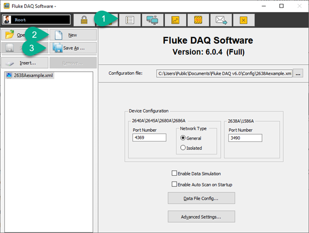
When you start FlukeDAQ, you will be seeing the generic device settings. To get back to this window at any time, click item 1 below: Configure Device Settings.. At this window, click New (2) to create a new configuration file (with the default name of unnamed.xml). Click Save As... (3) to name the configuration file and save it either in the default location or a location of your choice. For now, name the file "2638Aexample.xml". If you would like to edit this configuration later or edit another configuration file, you can click on Open... or the ellipsis (...) next to the "Configuration file:" path and select a file to load.
If you want to record data to a file during this example, click on the Data File Config... button and select a file name and directory location.
?
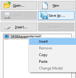
Next, right-click on the "2638Aexample.xml" in the configuration tree and select Insert to open the New Instrument Wizard:
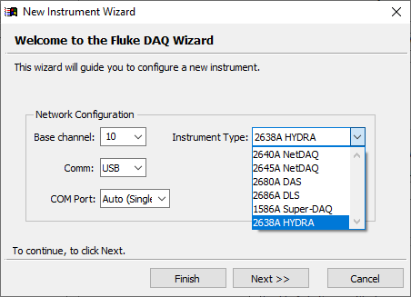
Select the 2638A from the Instrument Type: drop-down. Then set the Comm: to USB. Note you can specify the port manually by selecting one in the COM Port: drop-down. Please note that the "Auto" doesn't seem to work on all computer systems, so it is best to check your device manager for the virtual com port that was assigned by the driver and make sure it matches the one used below.
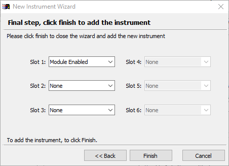
?When you click the Next>> button, it will tell you to ensure your instrument is connected. Clicking Next>> again will prompt FlukeDAQ to look for the device. When it is found you will have the option to configure the modules. If you have multiple modules, but only want to work on slot 1, you can select Module Enabled on slot one and set all others to "None". By default, it will list all identified modules installed in the unit. Click Finish when done.
?
Channel Setup
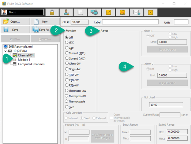
Now that you've added your 2638A to your configuration, you can set up the individual channels. In this example, you will see Channel 001 (the front Panel inputs), Module 1 (top slot in the back) and Computed Channels (you can do math functions here) (1). Selecting the channel gives you the ability to configure it for the function you wish (2), ranges (3), alarms and (4) other settings. The flexibility of these settings allows for more granular control of the device. For more advanced configurations, the settings are explained in the help file.
?
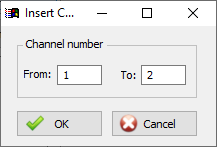
To add channels to the Module listing, you will right-click as you did to add the unit to the configuration. Doing this will present you with the Insert option and allows you to add channels 1-20 or any combination you want. Here we added channels 1 and 2:
?
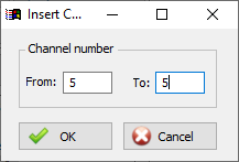
and then CH5 by itself:
?
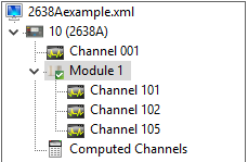
You now see Channels 101, 102, and 105 listed under Module 1.
?
Please note you can use the Label: block to specify names of the Channels:
?
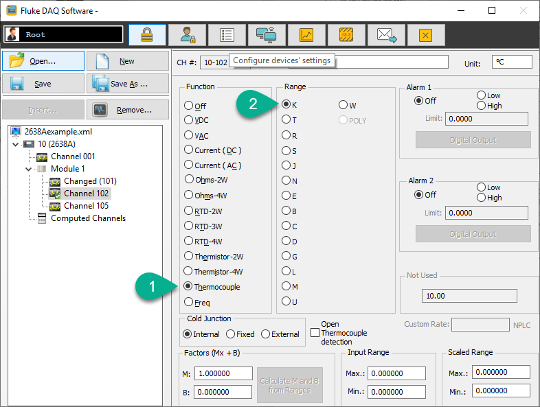
We are going to configure the Module 1, channel 102 for Thermocouple (1) A K type (2)):
?
Preparing a Scan
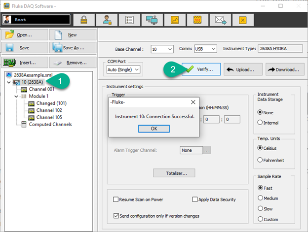
Save this configuration if you have not done so. Click on the 2638A in the list (1). Click Verify... (2) to ensure we have properly established communication.
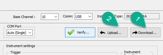
?Next Download... (1) the configuration -TO- the 2638A (push the configuration to the device). If you had configured the unit from the front panel, you can Upload... (2) those settings to FlukeDAQ on your computer. if download was successful, you will get confirmation with the message, "Configuration sent OK!"
?
In the Instrument Settings window you can configure things such as Interval (time between scans) and Duration (how long the unit should perform measurement efforts), and other settings described in more detail in the product documentation.
?
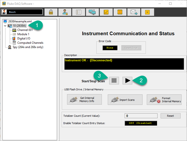
Clicking on the Communication button (1) allows you to start/stop the scan you've just created the parameters for. You can select the 2638A and press the Play (2) button to Start and the Stop block (3) to end the scan. You can control memory functions here as well.
?
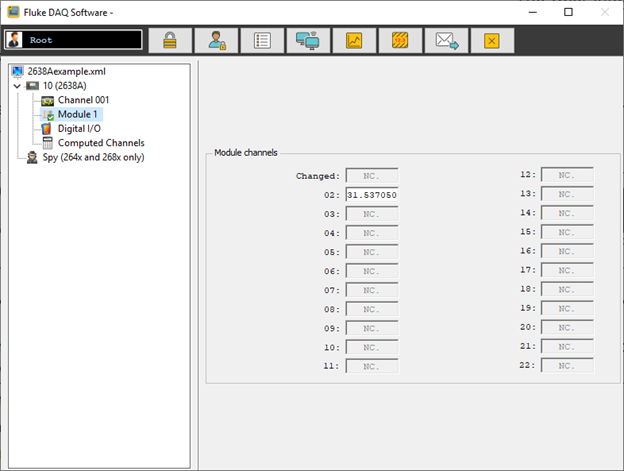
When the scan has started, you can click on the Channel 001 or Module to see the values observed by the 2638A:
?Conclusion
This is the basic process to get a scan started on your device. It should be straight forward when you understand that each step requires some instruction to FlukeDAQ, telling it what you want to accomplish. The underlying intent of the software is to enable you to configure and play the device from your computer instead of the front panel.
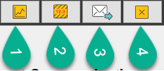
Outside of this setup process, you also have the option of Trend views (1), where you can see live-data and scale it for viewing and recording. The Alarms button (2) will show you information from configured alarm events. You can also have FlukeDaq send an email or configure a built-in web server for remote data viewing (3). And of course the Exit button for exiting the program (4).
More information can be found in the help file and other Knowledge Base articles that address specific processes.